


When we wanted to start investigating the influence of switches on streamers, it turned out to be pretty hard. We know it’s not in the audio data – we’ve shown that before – so it must be related to “noise”. And then – according to colleagues who know much more about it – especially common mode noise.

In order to measure common mode at very low levels, extremely sensitive equipment is required as well as complete isolation from the environment. After all: we don’t want to measure the environment.
After some research, we immediately added two devices to the Alpha Labs arsenal: an LISN, which stands for Line Impedance Stabilizer Network. And a CDN T8: a Coupling / Decoupling Network for Ethernet.
The LISN decouples the device to be measured from the mains and allows it to measure the noise caused by the device. LISNs are used to perform so-called EMC compliance tests. We use the LISN to isolate the device and measure the noise from the power supply. We chose a model from Tekbox and have now added the LISN-MATE to split common mode / differential mode noise.
Metal plate
In the picture you see a metal plate with the LISN on it as well as an elevation with the switch to be measured on it. Next to it is another blue box with a network cable and a measurement cable attached to it.
When testing with a LISN and a CDN (more on that later), it is important that both the LISN and the CDN share the same ground. The device under test should be lifted about 10cm, isolated from the rest of the set-up. This setup is important because it eliminates interference from external factors. Now we don’t do EMI pre compliance testing, but we want to get it right.
Coupling / Decoupling Network


With the LISN, we’re not there yet. We also needed to decouple the network as well as be able to measure the ‘port noise’ of the switch. So for that we purchased a so-called CDN: a Coupling / Decoupling Network. We chose a CDN-T8E from Com-Power (blue box). It works up to 230 MHz and can measure all four wire pairs.
Noise – some examples
Within a hi-fi system we always try to keep noise as low as possible. That means that every device in the chain counts. Also switches.
For a long time it was thought that switches could not mess anything up. After all, the ports are ‘galvanically decoupled’: a transformer in front of the network port ensures that everything is isolated. Data can get through nicely, but noise can’t…. so we thought!
Fact is: no galvanic decoupling is 100%. And when we started measuring the noise, we saw big differences.


Above you can see a Dlink 1210 switch. This one is quite noisy as you can see. Both low frequency (Prism measurement, white background) and high frequency (spectrum analyzer) you can see all kinds of noise. This is mainly due to the PoE power supply in this device.
The peak when measuring via the CDN is at -65dB. The LAN noise shows a lot of initial noise. Thereby, the noise floor is generally just very high. How do we know? Take a look at the measurements below!


Above you can see another switch: a Netgear GS108E. You can immediately see that this one is much quieter. Across the board. It is a switchmode adapter, so a little bit of clutter is to be expected. But you can immediately see that the noise floor is a lot lower than with the Dlink.
Especially on the LAN side, we are quite a bit lower: both low and high frequency. The Dlink 1210 peaks right at the beginning, then collapses and flips back up. The Dlink’s average noise floor is at -60dBm. The Netgear starts lower, goes to -67dBm, makes a bulge toward -62dBm and then drops back to -72dBm. That’s with a loaded port. Without load on the switch, the Netgear is at least 10dBm lower than the Dlink.
Common mode and Differential mode
Recently we have been able to split common mode and differential mode noise. This was previously also possible with the current probe, but it was a bit more difficult and less accurate. Now that is not so important to you. What matters is what it is and why we measure both.

Common mode noise is electrical noise that travels in equal directions across the + and –. It also moves through capacitive couplings to ground. These capacitive couplings can occur when, for example, two PCB traces – or wires – with different potentials are close enough together to generate a charge. A good designer tries to minimize this by keeping wires and tracks short and grouping them cleverly.
However, it can never be completely avoided. Common mode noise is mostly generated by these couplings. They occur, for example, in switching power supplies or digital devices with processors operating at higher frequencies. These circuits can interact with the rest of the device. After all, cabling and circuit boards are also indirectly just antennas.
Filtering common mode and differential mode noise requires a different approach. Common mode tends to be a bit trickier, but it can be reduced considerably by applying common mode chokes in the right places.
We find it interesting to see how well manufacturers handle this. Common mode is in fact very annoying in a hi-fi system because it can degrade playback quality by affecting the clock in a dac, for example.
Thanks for all your hard work on this.
All this noise ends up as leakage current into the cable which then feeds other parts of our system. Using isolators most of us thought we were squashing noise, but really it just ends up like a low pass filter for that stuff.
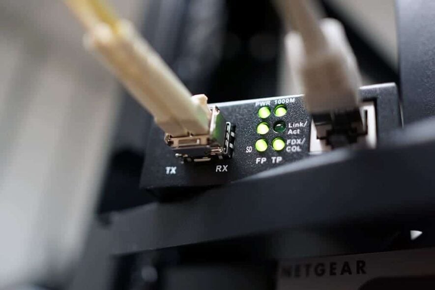
Really converting the Ethernet to optical then kills the leakage current… but conversion can increase jitter and so forth. Jitter leads to data errors which effects us as well.
Engineering is the minimization of diminishing returns.
Jitter in a network is different from jitter in a DAC or other digital audio-device. Jitter is an issue when you convert digital to analog or analoge to digital. In a network, you remain in the digital domain.
The thing with converting ‘copper to fiber’ is that you need to convert back from ‘fiber to copper’. So, eventually the dominant device is making an electrical connection to the streamer. And that device can introduce noise just as well. So you need to power it with a very clean PSU to prevent noise.
Jaap,
Actually jitter error is the same problem in audio, USB, Ethernet, PCIe or any other serial communication as it creates receive errors.
I was just watching a video from Keysight on EYE patterns and jitter calculation this morning and they had a real good graphic on this.
Since the receive clock is trained on the preamble of the packet, a signal with more jitter will create false 1 and 0’s which then the CRC will fail. Depending on the protocol that packet maybe resent or the error ignored.
I have the USB Compliance setup from Tektronix here and high speed USB with longer packets, especially DSD over DoP will cause errors because the receive clock may vary more than the transmit clock over a longer packet.
Since isosynchronous is not error correcting this leads to errors in the sample which leads to errors in the DA process. Of course most of that is averaged out, but it still creates a problem.
In FPGA design you reduce receive jitter by sampling the input x# of times over the receive clock and determine the correct 1 or 0.
… and yes power is important all the time. Switching supplies effect the ground noise so much in a lot of designs.
Almost forgot, this is also why a really good low jitter oscillator makes all the difference in the world on transmitting a valid low jitter serial data stream. I cannot figure out why people are using these 10Mhz clocks with PLL to create audio (usually a multiple of 11.2896 & 12.288Mhz) or USB (usually a multiple of 12MHz) or Ethernet (usually a multiple of 25Mhz).
If jitter is bad enough, you will get errors. Of course… But honestly: I haven’t seen that on a network, yet. I run managed switches in the office and have not seen any errors or CRC-corrections due to jitter.
But even when that happens: it will get corrected and because of buffering, people won’t even notice it. That has nothing to do with the sound quality in the end. The noise a switch generates does… so I is useful to look at that.
For USB, I don’t have the gear to test it properly. So I can’t say anything about that.