



A while back we made the first set of measurements on an optical network connection. That article can be found here. We have now done some additional measurements. Not that we are done yet, but we do want to share this series with you because we made an interesting discovery.
In the first article, we already demonstrated to some extent that a fiber optic link is not immune to noise. In this second set of measurements, we used a similar setup, but also worked with a 1 MHz signal to see what pops up…
We also tried to inject noise into the cables with a current probe and worked with two fiber converters to see what power supplies and modules do when it comes to noise.
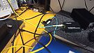
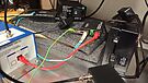
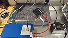
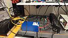
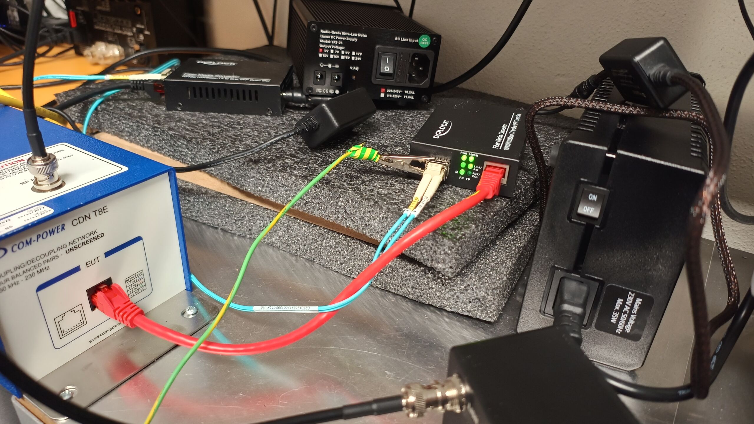
The setup is pretty much the same. In this setup, we made two setups. In both setups, the device under test is completely isolated with a network CDN as a LISN (for isolation of power supply).
Setup-1
Dlink-1210MP switch –> fiber to Delock converter –> CDN (isolation/noise measurement –> UTP cable to external switch for network activity.
Setup-2
Dlink-1210MP switch –> UTP to Fiber converter (for network activity) –> fiber to Fiber converter –> CDN (decoupling / noise measurement) –> UTP cable to external switch for traffic emulation.
We also tested a closed loop; this does not work with the Delock kit but does work with the unbranded version. It did not matter in measurements because the CDN and the LISN completely isolates the device under test.
First series: measurements between two converters
In this first series of measurements, we connected two fiber converters together to see what a power supply does and whether we can inject noise with a current probe. We mainly use a broadband noise signal (30 MHz).
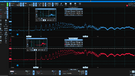
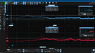
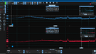
This first series was done with a cheap fiber converter with both standard power supplies, an Sbooster BOTW 5V on the receiver and an Sbooster BOTW on both transmitter and receiver.
It can be seen that the noise drops tremendously when we replace the power supplies. But interestingly, the noise is not completely gone when we replace the Sbooster only on the “receiving” side (this is the side we measure). In short: some of the noise from the dirty, switching power supply comes along through the fiber optic link!
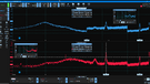
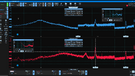
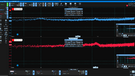
In the top three measurements, we made a ‘loop’ between the unbranded fiber converters. This was to exclude the Dlink as the ‘source’ for a while. This ultimately made no difference in the results.
We made a baseline and then injected noise into the utp cable via a current probe on the transmitter side and receiver side. On the receiving side we do see noise back, because this cable is directly connected to the CDN. However, if we inject on the transmitting side we see no noise back on the scope. This is interesting and somewhat unexpected.
It could be that the influences we see are mainly due to power supply polution. If the noise cannot get into the power supply, it could have no (or less) influence on the modulation errors we measure back at the receiving end. However, we are going to make some additional measurements to rule this out.
Noise and 1 MHz injection with the Dlink switch
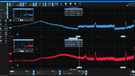
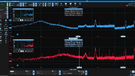
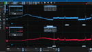
In this test, we paired the Dlink switch with FS-optical SFP module with a Dlock fiber converter also with an FS-SFP module. Initially, we do a baseline measurement. Then we add 30 MHz noise. And finally, we also inject a 1 MHz sine wave. In both cases, we inject this into the Dlink switch with a modified UTP-cable we connect to the function generator. We measure on the side of the Delock fiber converter.
In the case of the wideband noise, we simply see the noise floor go up a bit. Differential mode noise in particular goes up. We’ve seen that before as well, so it’s independent of the brand or type of converter. Although there are subtle differences in that as well.
In the case of the 1 MHz sine wave we inject, we see it reflected beautifully in our measurement! We did not expect that! This shows – as far as we are concerned – that noise is indeed modulated and travels with us over a fiber optic connection.
Check out the video!
Conclusion
Can noise ride along over a fiber connection? Yes… it certainly can. We see broadband noise as well as the 1 MHz sine wave pop up on the scope. Is it attenuated? Yes… of course, but it’s not gone, as many will expect with optical decoupling. After all: electrical noise cannot drift along over a fiber link. However, noise can, therefore, be modulated on the signal….
To be continued!
very very very interesting… I already have build my optical network (2 SFP and few meters fibre in between, power supply: 2 separated LPS) but use components quite entry-level… waiting for your next episode to evaluate upgrades/tricks
thks in advance 🙂
Prompt in Spanish. After, translation to English
[ removed content copied from ChatGPT or one of the other services]
[editor comment:] Copying and pasting (large) pieces of text from a AI service is not wanted.
– The content is not a comment.
– Those models are trained on often illegal scraped text. Same is true for original content produced by Alpha Audio.