
Intro
Contents
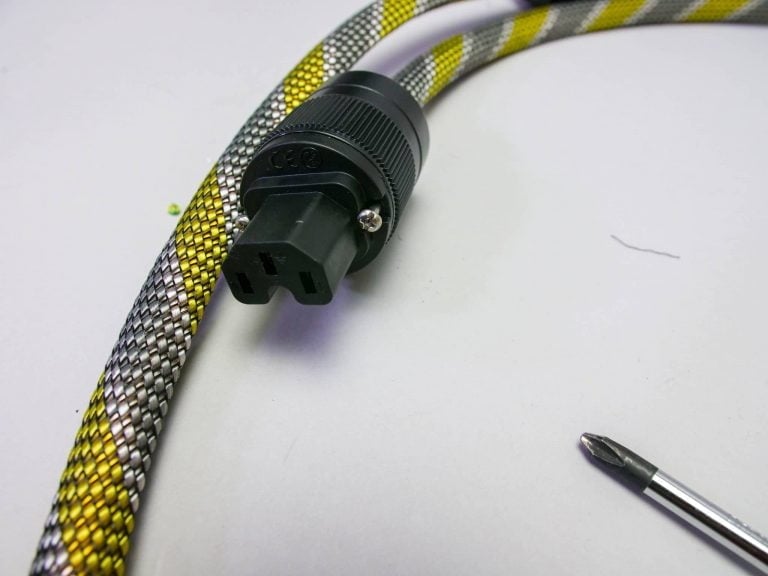
After the DIY double shielded network cable we got the hang of it. Partly due to the many questions whether this construction of double shielding connected at both ends, works with every cable. Well… we’re just going to try it! We buy two meters of VMVK cable at the hardware store, grab our roll of copper foil and two meters of sleeve, and get a set of nice connectors. In short: we are going to make a DIY power cord…!
NOTE: There are a lot of great cables for sale in our industry. And the brands that supply these products have, in some cases, done decades of research on what works and what doesn’t. So we are not at all pretending that we know better and can do better. We do these little studies purely to learn from them…. because if we understand things better, we can explain them better to you.
So don’t see this ‘workshop’ as a “How To” to make your own high-end power cable. It is purely for learning purposes.
A bit of theory
What we have noticed when comparing network cables is that the cable with the shielding connected at both ends just sounds better. Sharper in focus, more stable…. so on and so forth. And at home with your author, the effect is exactly the same. In short: it is reproducible in this case…. That’s always nice, because it means we’re on to something.
This post generated quite a few responses on Facebook. The question was: what about powercables for example? Does the shielding have to be connected at both ends there as well? Well, some reading and research tells us that this is still quite complex, but that in certain cases it can work better. Think of the exclusion of HF (High Frequency) and EMI (electromagnetic interference). … But let’s go back one step.
Let’s start by saying that with network cables, the network standard specifies that a shield must be connected at both ends. If currents then start flowing – something that, for example, can happen with PoE devices – e.g., 802.3AF, AT… – and a hum is generated, then the installation has not been done correctly. The solution is not to disconnect the shield, but to tackle the problem at the source.
With other signal cables – balanced as well as single ended – and mains cables it is common within HiFi to connect the shield at the source side and to leave it loose at the other side – the receiver. With signal cables, this is done to prevent hum. Many enthusiasts think that this is a ground loop, but that is not always the case; it can also be other currents that the cause of the hum.
However, here too the solution is not to remove the shielding completely, but to solve the problem: where does the potential difference come from? Usually it comes in through the ground…. Then ground all devices correctly to get rid of the problem, right? Then you tackle the primary problem immediately and you can enjoy a better shielding.
A few quotes
A few quotes from professionals in documents we have read (for example: AES, Nutwooduk, Wiki Talks and EMCstandards.co.uk)
AES: “When a shielded connector is used, it should be of a type that provides a connection having the lowest practical impedance at radio frequencies between its shell and the shell of a mating connector” … “If for any reason the shield connection of wiring that interconnects audio equipment is interrupted to prevent the flow of current in the shield, the interruption shall be exteral to the equipment. It has been shown that, in the general case, the interruption should be at the receiving end only.”
WikiTalks: “The cable shield works best when the signal lines are completely surrounded by a conductive “tunnel” that is completely at ground potential. That means it should be grounded at BOTH ends (grounded at one end means the other end is similar to an antenna at some frequencies). But to prevent ground loops, both devices have to be at the same ground potential (otherwise current will flow on the shield). That means lots of high quality ground straps between both ends. Think of it this way, if everything in the installation were sitting on a 12 inch slab of pure copper, and bonded to it, how could a ground loop arise? It couldn’t, as long as all the components in the installation are connected correctly and have not failed. In a real world application, the real solution is to reduce the slab of copper and the bonding to something practical (lots of conductive straps between all components), and to watch that all components are installed correctly and to the same standards. This is the infamous Multipoint Ground.”
WikiTalks: “There is a very good reason why ordnance standards require wire and cable shields to be grounded at both ends. (Reference: MIL-HNDBK-1512, MIL-STD-1576, MIL-STD-1542, among others) To use lightning as one example for grounding at both ends disregards the need to do so in almost all applications. Grounding at one end only to prevent groundloops has gone to far into EE designer folklore, so much they will ground coax signal cable shields at one end only with distastrous results. Grounding at both ends is the only way to intercept magnetic fields and reduce their coupling to the interconnecting wires.”
EMCstandards: “The shields should be “bonded” to the boxes at the ends of their respective cables, not earth ground, building ground, or anything else. Military standards like Mil-Std-188-124B and the FAA get it right. It’s time for everyone else to also.”
Bubbles
Of course, we also called some of the leaders of the Dutch hi-fi industry to validate things. Actually, the parties we called agree that a good cable is sheathed at both ends. Especially with XLR, digital cabling and network cabling. This is because the primary goal there is to keep out HF-noise and EMI. With single ended cables and mains cables, it sometimes works slightly differently because other factors come into play.
For example, the shield in a single ended cable often works as a return. In short: the shield is not really a shield and also sends all noise into the amplifier, because this is simply seen as an audiosignal. In that case, other solutions are also possible. That does not mean that one side is just loose – certainly not with RCA – but that, for example, a capacitor is placed between the (extra) shield and ‘ground’. In this way, for example, HF is blocked and LF (low frequency) can pass through.
A shield that is loose at one end remains simply an antenna and can even adversely affect the signal cables. The idea that noise runs off through the one point that is connected is not correct. The shielding simply captures signals and, in the least favorable case, transfers them to the neighboring conductors. And that is the last thing you want.
Especially with mains cabling (with a +/- and ground): what do you want to keep out (or in?) with the shielding? Do you want to keep HF out completely? Then you better connect both sides. In other cases, a capacitor coupling at the other side may be a better solution. We estimate that with mains cables, the main issue is that you want to keep the magnetic field inside the cable. Especially if there are other signal cables next to it. In that case, a shield that lies loose is completely useless; it will not keep any magnetic field inside.
“The key to magnetic shielding is to reduce the loop area. Use a twisted pair or the return of the current through the shielding. To prevent the radiation on a conductor, a grounded shielding on both sides is normally used above the cut frequency, although a few precautions should be taken.” (source)
Now this – we have read and heard – is complex stuff. Not so much the theory, but mainly because of the variables. Because a lot depends on the equipment the cabling is connected to. Where is the ground connected? Is the equipment actually grounded? And are all the grounding points the same? How are the electrics done? So on and so forth. In short: sometimes there is no right or wrong. At least not with power-cables or single ended cables. But with network cables, coax and balanced cables, there is actually right and wrong… :-).
Our conclusion summarized:
- It is a bit of an old idea – within hifi – to shield cables on one side by default. AES once reported this in ’53.
- Shielding at one end simply creates an antenna and does not actually solve the problem of ‘hum’: it is symptomatic.
- A shield connected on one side simply works poorly, and in some areas, not at all.
- Shielding at one end may even introduce additional problems in some cases.
- Shielding on both sides sometimes has drawbacks as well….

