
Intro
Contents
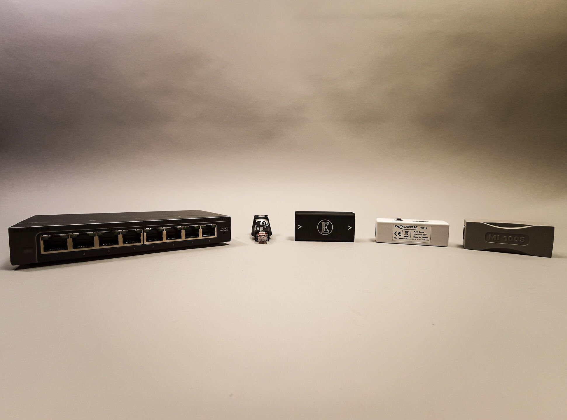
Keeping an open mind is important. Both in our lives and in our profession. If we as a human race don’t keep an open mind, we are basically at a standstill, as we would be dismissing everything we don’t know. However, at Alpha Audio we also think it is important to understand things. We like to find answers to our ‘why’-question. Now… we’ve done two big switch tests. The first one was a blind-test with readers. And the second – partly due to the wonderful virus – without an audience. In both cases we observed differences. Is that crazy? Well… no… it is, in fact, measurable. And in this article you will find our findings!
Measuring digital equipment is a profession in itself. Both creating a good set-up and interpreting and performing the test is not easy. Or cheap. So we didn’t do these measurements ourselves. And perhaps that makes it more interesting, because: do our findings from the listening test match what the measurements say?
The test setup

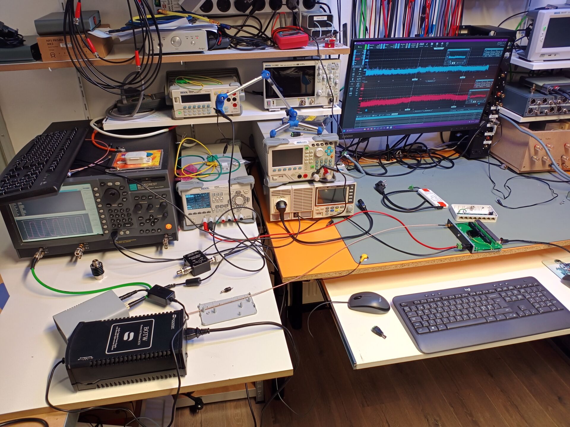
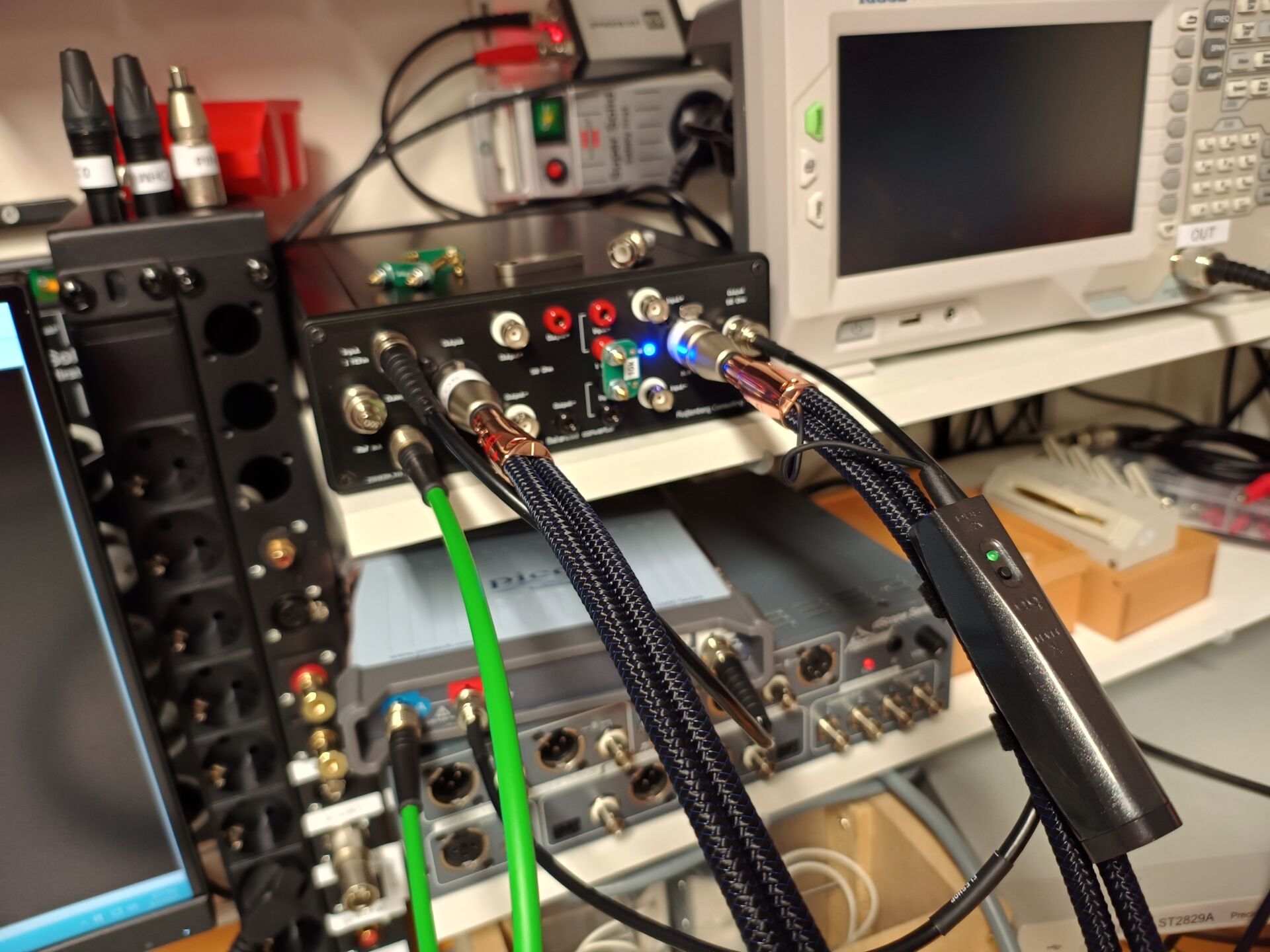
In a nutshell, the switches were measured as follows:
- The network side of the switch is connected via a CDN M3.
- The Ethernet side is connected to and CDN T8.
- When measuring on one CDN, the other port was terminated with 50 ohms.
- There is measured on the various ports: 1-8, the interference level is identical for all ports (as we may expect)
By the way, in this case a CDN is not a Content Delivery Network but a Coupling / Decoupling Network. These are needed to isolate the circuits under test so that there are no external sources of interference. Crucial in this case because the noise levels are already very low. And we want to keep it pure. 
What we are interested in is common mode interference. In this case, it’s common mode current that could be going through the Ethernet port into the streamer and/or pass through to the dac or amplifier.
But on the other hand, we would also like to know what is going through the power supply itself into the mains. That way, noise can also find a way into the system. Because that can also lead to distortion of the reproduction.
A brief word about common mode current: Common mode current is the sum of the currents through a cable. Normally it is 0 since the current through signal and return conductor are equal and opposite. It is called common mode interference if the direction of the interference currents in both conductors have the same direction.
Common mode interference can manifest itself by common mode to diferential mode conversion. This conversion can take place in a DAC and cause jitter there, or distortion in the analog backend. Something similar can also take place in the amplifier.
In principle, common mode current can be filtered and thus reduced. However, one filter is not equal to the other, as we will see in the measurements.
Also, the quality of the power supply determines the incoming interference level and therefore what remains of that noise at the Ethernet side.

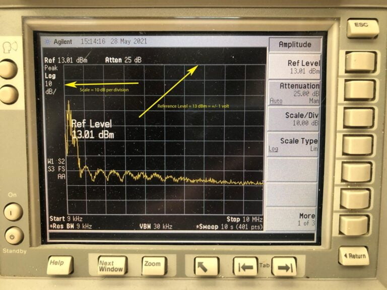
In the example above we have indicated with arrows how you can read these measurements. The bandwidth between which we measure is 9 kHz – 10 MHz. The base – reference – is 13.01 dBm which corresponds to 1 volt. That is the top line. Per division, 10dB is subtracted. In short: at the bottom we are 100 dBm lower. But the best switch doesn’t get lower than the third dash from the bottom (above the 2nd div), which is -70 dBM below the 1 volt reference (13 dBm). And that corresponds to 300 uV. That’s low. Most peaks are on the power supply side around 70 mV.
What about data?
Some enthusiasts sometimes say that the data is corrected over the network, so no errors occur and therefore there can be no audible difference. That no data errors occur with proper transmission is absolutely correct. We have already checked this regularly. But that’s not where we need to look… Our reasoning was simple: we hear a difference, it is not in the data, so where is it? What remains is noise….

